Guitar over Cat5 project 3
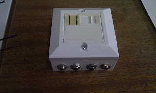
Monday 04 July 2011 at 5:24 pmThe stage end now looks like this:


In a metal box for protection from drunken dancing audience members with uprated jack sockets.
Inside view:

Next week - testing live!
The stage end now looks like this:
In a metal box for protection from drunken dancing audience members with uprated jack sockets.
Inside view:
Next week - testing live!
Moved into phase 2, here’s what I have now:
Basically a Cat5 socket connected to 4 bits of guitar cable with jacks on the end, and;
and a Cat 5 socket connected directly to 4 jack sockets.
My stage guitar rig can be a bit of a bind when setting up and breaking down – it’s configured thus:
Guitar plugs straight into amp
Effects send to Boss GT8 pedal
Output from GT8 to effects return
Additional cable from GT8 to footswitch allowing GT8 to switch channel

So all in all 4 cables involved. I wanted to try & cut down, initially by using a 4-pair multicore, then I could bring the guitar input down to the floor, keeping to a single cable run.

But multicore can be a bit expensive, and I’m an IT network technician with access to lots of Cat5 cable, so I started to wonder… Could I run the whole thing over Cat5 UTPnetwork cable, put a RJ45 socket at either end then all I’d need is a patch cable of the correct length.
No-one as far as I can see on several Googlings has tried it, so the only way to find out is to experiment.
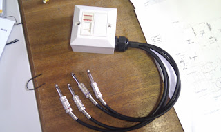
Today I have this:

which is an old guitar lead soldered to one pair of a bit of Cat5, punched down onto a socket module
and this

which is Cat5 cable punched down into a module with a jack plug on the end
Plug in the lead to my guitar, plug the 2nd bit into an amp*, connect with a 5m patch lead and… bingo! It works! No apparent loss of signal strength or quality.

*I did use a proper amp to test – the mini-Marshall is just to show schematic!
Next step is to put in the other channels and see if there’s any crosstalk, hum or interference with the FX loop running backwards & forwards. Watch this space.
As requested by my friends at Carpe-TDM here's some more pics of my handguards.
They're Acerbis Rally II's whose website is HERE. They were an easy fit, and have stayed put ever since I put them on, about 4 years ago. If you're leafing through the Acerbis catalogue, I also used the 'ATV fitting kit' which is no more than a stand-off for the inboard end. The bar end weights had to go, so the Acerbis expanding bolt fitment went straight on. Excuse the grubby state of the bike!
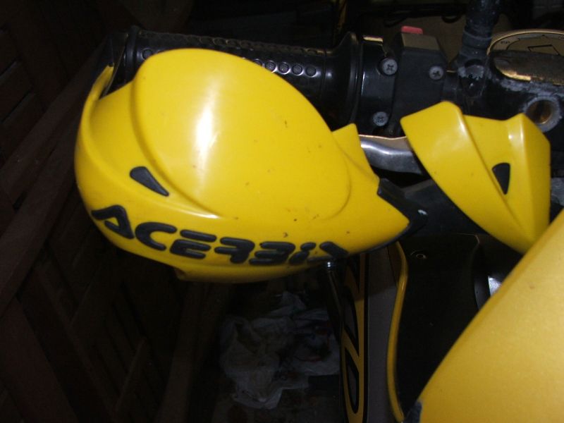
Front view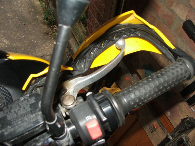
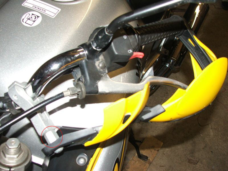
Top views - you can see the stand-off hex bolt thing above.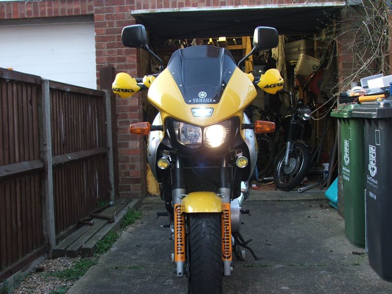
The end result
Here's some piccys & words following my installation of fog/spot/aux lamps on my MK2 TDM850.
I originally fitted some cheap LED units, but the bulbs started to fail, and of course they can't be replaced. So I found these halogen ones on good old eBay. Shipped direct from Bulgaria (yes!) and I think they look pretty sturdy. Includes mounting brackets and relay/wiring. Boffo.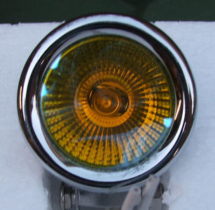
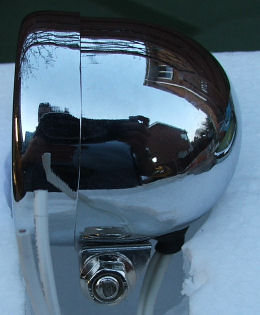
I expected H3 bulbs in these, but it turns out they're sealed dichroic MR16 bulbs. So easily replaceable, and there's even LED bulbs available (obsessed with LEDs? Me? A bit...)
Anyway, off to the garage, out with the allen keys and sidepanels, screen and inner fairing off. As I'd previously run the old lights straight off the sidelight circuit with a dashboard switch, I used this wiring to run the relay. I mounted the relay behind the sidelight (stubby screwdriver required here).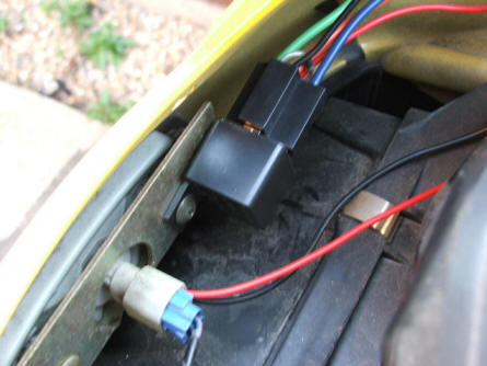
Next is to run the power direct from the battery. I connected a ring crimp connector straight on to the battery terminal next to the main fusebox via an inline fuse, then ran the cable following the main harness under the airbox. (Wiring got tidied up later & fuse holder strapped in)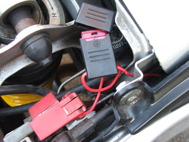
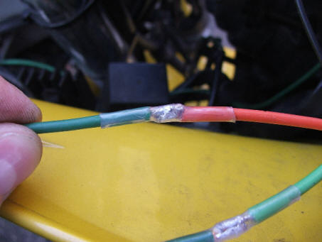
Then connect it all up; that concludes the live side of the installation. The earths for the lamps were wired to the fairing stays on each side. Pic shows earth point and the route of the main feed wire (green - it was all they had in 17amp). I mainly used insulated crimps for joins where I might need to disconnect in the future, but some I soldered & insulated with heatshrink. 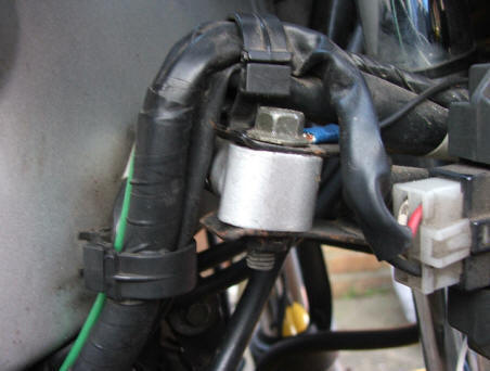
Mounting the lamps was a single hole drilled in the lower fairing, and the brackets bolted through. Bracket pic: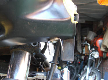
Lamp mounted; sidepanels still off: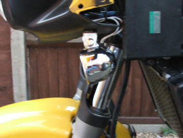
Finished article - the camera decided they were too bright & adjusted the aperture, so not a direct comparison, but you can tell how bright these are: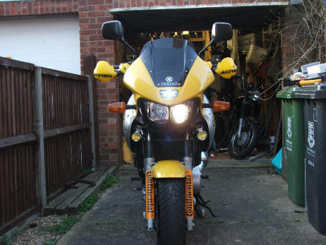
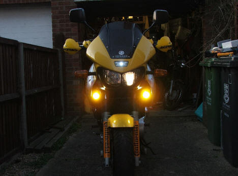
The only drawback is that there's no 'focusing' of the beam. It's a wide pattern so even angled down they're dazzling. Having looked around a bit there are several bulbs available with a narrower focus for a bit more control. Should make night rides a bit safer though.
And previous readers of the Carpe thread may recall the amazing wording on the pack of the original lights. These ones are no exception: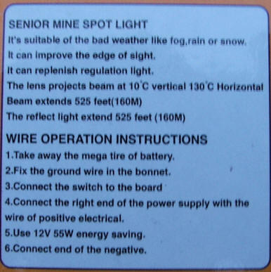
And finally - these are my trusty £2 QD kneepads which are invaluable for crawling around under cars & bikes: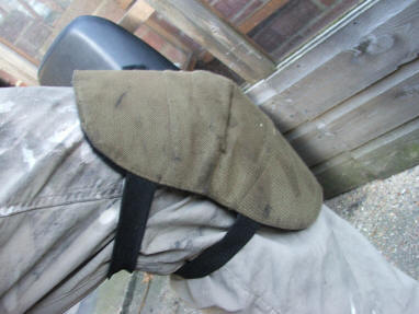
And my other very useful home-made invention - the Daniel Park-O-Matic keeps your bike upright in the garage, giving more space without hauling the paddock stand out. It's a bit of 2x4 with a slot drilled in it. I'm thinking of taking it to Dragon's Den, what'd you reckon?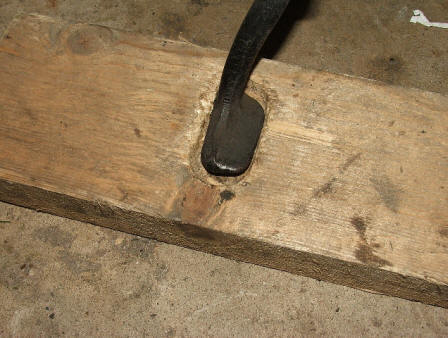

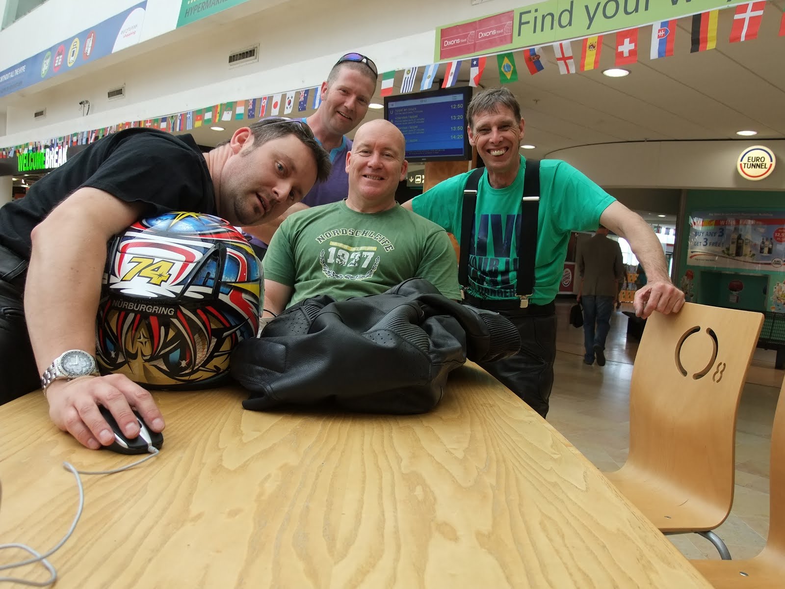
I built a shutter release switch for my Fuji S200EXR out of an old mouse. This is the circuit diagram. The idea came from this website www.trafficshaper.com, where there’s a view of the inside of the RR-80. As it’s only 3 resistors and a couple of switches it was pretty straightforward to build, although it’s impossible to find a 2-stage shutter button switch without actually dismantling a camera!
The other difficult bit is getting the Mini-B USB plug. I got mine as a solderable one from Maplin, but it only connects to the standard 4 USB pins. The 5th pin is what’s required here, so I had to modify the plug, too.
So on my otherwise standard-looking mouse left-click is focus, right-click is shoot. More details and pictures available if anyone’s interested. Here’s a pic of it in action to take a self-portrait with some burly bikers!